



Off-Grid Solar Systems: Integrating Pure Sine Wave Inverters with Batteries and Controllers
- Quick Answer
- Introduction
- 1. Define the Modular Off-Grid Solar Architecture
- 2. Translate the System Requirement Into Interface Inputs
- 3. Coordinate a Pure Sine Wave Inverter for Off-Grid Solar Across Operating States
- 4. Validate the Same Scenario Against the Connected Configuration
- 5. Convert the Modular Requirement Into a Controlled B2B RFQ
- Key Takeaways
- FAQ
- Request a Modular Off-Grid Solar Integration Review
Quick Answer
A pure sine wave inverter for off-grid solar can operate within a modular system in which a separate solar charge controller manages charging from the PV source, the battery-side DC system provides a shared electrical interface, and the inverter supplies AC power to approved loads.
Once the component requirements have been established, the integration task is to determine who owns each function, what information crosses each equipment boundary, what should happen when solar availability changes, and what evidence is needed to accept the connected configuration.
Pure sine wave output alone does not establish built-in MPPT charging, AC battery charging, automatic transfer, load management, BMS communication or compatibility with a particular battery. Any required function must be assigned to equipment that is documented and qualified to provide it.
For B2B procurement, the resulting deliverables are a defined modular topology, interface inputs, operating-state requirements, connected-system acceptance evidence and a controlled RFQ.
Introduction
A modular off-grid solar system brings together equipment with separate responsibilities. The solar charge controller regulates charging from the proposed PV source according to its documented capabilities and the battery’s requirements. The battery-side DC system is shared by charging and inverter supply. The standalone pure sine wave inverter converts suitable DC input into AC power for the approved loads.
The devices may be supplied by different parties, but the project still needs one coherent operating requirement.
An inverter can satisfy its individual AC specification while leaving unresolved questions about the battery’s discharge limits. A controller can accept a proposed PV source while still requiring confirmation of its battery-charging interface. A battery may appear suitable for both devices individually without establishing how the connected arrangement should behave as solar input falls, charging stops or the next operating cycle approaches.
These questions matter to distributors seeking repeatable configurations, integrators coordinating equipment responsibilities, transportation and outdoor partners facing variable charging conditions, and professional or commercial buyers requiring a documented acceptance basis.
This article begins after individual components have entered a defined candidate range. It explains how separately supplied inverter, controller and battery functions are handed over, coordinated and verified across changing off-grid operating states—not how to size each component or qualify an integrated MPPT product.
Full load, battery and PV calculations belong in the off-grid inverter, battery and solar sizing guide. The different arrangement in which MPPT charging is integrated into the inverter is addressed in the inverter with MPPT charger architecture guide.
The engineering sequence for this page is:
Modular Topology → Interface Inputs → Operating-State Requirements → Connected-System Acceptance Evidence → Controlled B2B RFQ
The objective is to define a configuration precisely enough that every required function has an owner, every important state transition has an expected outcome, and any unresolved qualification item remains visible.
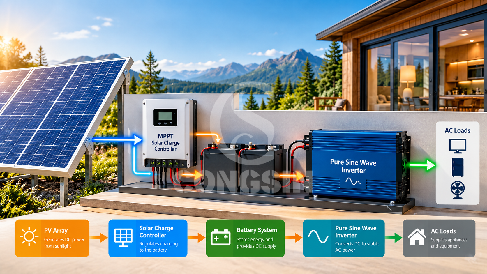
1. Define the Modular Off-Grid Solar Architecture
Before reviewing equipment interfaces, the project must define which device is expected to perform each function.
For this guide, the conceptual arrangement is:
PV Array → Separate Solar Charge Controller → Shared Battery-Side DC System → Standalone Pure Sine Wave Inverter → AC Loads
The arrows describe functional relationships, not an installation drawing or a mandatory sequence in which every unit of solar energy must first be stored and later discharged.
The shared battery-side DC system may be involved in charging and inverter supply concurrently, depending on the actual configuration and operating conditions. Its physical arrangement, protection, isolation and installation requirements must be established through project-specific design and applicable equipment instructions.
Map the Energy Path and Assign Functional Ownership
The first architecture record should be concise. Its purpose is to prevent an important system function from becoming an unassigned assumption.
| Required function | Expected equipment owner | Boundary to establish |
|---|---|---|
| Solar charging | Separate solar charge controller | Proposed PV source and battery-charging requirements |
| Energy storage and battery limits | Battery system and BMS, where applicable | Permitted charging, discharge and protective behavior |
| DC-to-AC supply | Standalone pure sine wave inverter | Shared DC input and approved AC loads |
| Additional charging, transfer or control, if required | Specifically assigned equipment or operating procedure | Actual supported function and responsible party |
For example, specifying a pure sine wave inverter does not establish who provides AC-source battery charging or automatic transfer if either is required. Those functions need their own equipment and responsibility assignments.
Likewise, identifying a BMS does not prove that the inverter or controller can exchange information with it. A project requiring communication must identify the intended function and verify support at the actual equipment level.
Distinguish Modular Equipment From Integrated Functions
This guide addresses a standalone inverter paired with a separate solar charge controller. An inverter with integrated MPPT changes where the charging function resides, but it does not remove the need to qualify the applicable system interfaces.
The detailed comparison and qualification of integrated MPPT architecture belong in the existing integrated inverter and MPPT guide.
Buyers may review the CONGSIN pure sine wave inverter range and MPPT solar charge controller range as separate product directions. Those category pages do not establish that any particular inverter, controller and battery combination has already been approved together.
Stage 1 deliverable — Approved Modular Topology: the proposed functional arrangement, equipment ownership and functions still awaiting assignment.
2. Translate the System Requirement Into Interface Inputs
Once the topology is defined, the next task is to transfer the project’s existing requirements to the correct equipment owners.
This chapter does not repeat inverter wattage calculations, battery-bank sizing, MPPT controller sizing or BMS current selection. Those processes establish inputs. The integration process must ensure the inputs reach the appropriate interface and that a responsible party supplies the relevant evidence.
Transfer the Load and Battery Requirements
The inverter qualification process needs the approved AC load requirement, destination AC version and applicable battery-side operating conditions.
The battery qualification process needs the inverter-side demand and the relevant operating conditions. Nominal battery energy alone does not establish that the proposed battery can supply the inverter under those conditions.
Where battery protection or communication is required, the interface record must identify the required behavior and the device expected to provide it. It should not substitute a generic statement such as “BMS compatible” for model-level confirmation.
Transfer the Solar Charging Requirements
The separate controller receives two distinct inputs: the proposed PV source and the selected battery’s charging requirements.
The party responsible for the controller must assess the proposed source against the documented controller input limits and assess the charging output against the battery requirements. The integration article need not reproduce the calculations used to select the controller.
The resulting handover can be kept to one record:
| Interface | Information to transfer | Evidence owner or unresolved item |
|---|---|---|
| AC loads → inverter | Approved load conditions and destination AC version | Proposed inverter documentation and load assessment |
| Battery → inverter | Applicable DC conditions and discharge requirement | Inverter and battery/BMS documentation |
| PV → separate controller | Proposed source and operating conditions | PV information and controller documentation |
| Controller → battery | Charging requirements and restrictions | Controller and battery documentation |
| Shared DC system | Connection, protection and concurrent-operation requirements | Project engineering responsibility |
| Optional control or communication | Required function, if any | Confirmed equipment support or an open item |
An interface input is not an acceptance result. If an exact model, operating condition or supporting document is missing, that row remains pending rather than being described as compatible.
Stage 2 deliverable — Interface Input Record: the approved requirements transferred to their equipment owners, together with evidence responsibility and missing information.
3. Coordinate a Pure Sine Wave Inverter for Off-Grid Solar Across Operating States
The interface record identifies what each device must support. It does not yet establish how the connected system should respond when operating conditions change.
A modular system therefore needs a separate operating-state requirement. This requirement defines the relevant transition, the behavior the project expects and the equipment or party responsible for providing it.
Define One Scenario Across Changing Solar Conditions
Consider a hypothetical project scenario: approved AC loads must continue as solar input decreases; a period without dependable charging may follow; charging later becomes available again; and the battery must reach a defined state before the next required operating cycle.
This scenario is an illustration of the qualification method. It is not a CONGSIN product specification, a completed test or a guaranteed runtime.
At the start, the proposed PV source is available. The project requires the inverter to supply the approved AC loads while the separate controller operates within the appropriate solar-input and battery-charging conditions. Whether the battery is charging or discharging at a given moment depends on the actual system balance.
As solar availability falls, the project must define whether battery support is permitted, which AC loads must continue and whether any load reduction is required. It cannot assume that a standalone inverter automatically performs load shedding or coordinates a programmable response with the controller.
If dependable charging becomes unavailable, the approved no-charge requirement defines the retained loads and planned stopping condition. When an accepted charging opportunity returns, the project defines what battery state must be restored before the next operating cycle.
| Operating-state transition | Trigger or defined condition | Required behavior | Functional responsibility to confirm |
|---|---|---|---|
| Solar available | Proposed charging source is available under the defined conditions | Supply approved AC loads and permit suitable charging | Controller, inverter and shared DC system |
| Solar becomes insufficient | Available solar contribution falls relative to the required operating condition | Apply the approved policy for battery support and retained loads | Inverter, battery and any separately required control function |
| Dependable charging becomes unavailable | Project enters the approved no-charge scenario | Supply retained loads only within the defined operating boundaries | Inverter, battery/BMS and any assigned operating procedure |
| Charging opportunity returns | Confirmed charging source becomes available | Resume suitable charging and work toward the specified recovery target | Source, controller, battery and concurrent-load responsibility |
| Next operating cycle approaches | Defined recovery deadline or restart condition is reached | Establish whether the required starting state has been restored | Project acceptance or operating responsibility |
These transitions are requirements to assign, not evidence that every proposed product contains an automatic state controller.
If the project needs automated load management, source switching, supervisory control or communication, it must identify the specific function, the equipment expected to perform it and the evidence needed to confirm that capability. Where operation is manual or procedural, that boundary should also be explicit.
Define the Stopping and Recovery Conditions
The planned stopping condition should be inherited from the approved storage operating requirement, not invented during inverter integration.
In the no-charge state, the project must establish which loads remain supplied and the condition at which planned operation must stop. It must not credit solar generation that has not been established as dependable for that scenario.
Recovery is a separate requirement. The buyer must specify the state to be restored, the relevant deadline, the confirmed charging sources and any AC loads that continue operating during the charging opportunity.
The existence of a controller, or its headline rating, does not establish that recovery will finish before the next cycle.
Detailed load timelines, autonomy energy, protected reserve and recovery-energy calculations belong in the storage planning guide. This article uses those approved results as inputs to the connected-system operating requirement.
Stage 3 deliverable — Operating-State Requirement: one traceable sequence of changing solar conditions, each with a defined trigger, expected behavior, responsible function, stopping boundary or recovery criterion.
4. Validate the Same Scenario Against the Connected Configuration
The operating-state requirement from Section 3 now becomes the basis for connected-system acceptance.
The distinction is important: a requirement describes what should happen; qualification establishes what the proposed configuration has been shown to support.
Individual product documentation can establish declared capabilities and limits. It does not, by itself, demonstrate every required behavior of a connected inverter, controller and battery as conditions change.
Translate State Transitions Into Acceptance Evidence
Use the same illustrative scenario rather than creating a new technical checklist.
The project begins with available solar input, moves through falling solar contribution and no dependable charging, and then enters recovery. Each transition should be assessed against the already defined load policy, equipment interfaces and operating boundaries.
| Requirement from the Section 3 scenario | Connected-system behavior to establish | Evidence required before acceptance |
|---|---|---|
| Solar is available | Approved AC loads remain supplied while suitable charging is permitted | Proposed equipment limits and, where required, evidence of concurrent operation under the defined conditions |
| Solar input declines | Approved loads continue according to the permitted battery-support policy | Inverter and battery-side response assessed against the specified transition |
| No-charge state begins | Retained loads follow the approved operating requirement | Storage requirement, applicable equipment limits and verification of any required control behavior |
| Planned stopping boundary is reached | Required protective or operating response occurs without assuming an unassigned function | Applicable device documentation and connected-system evidence where required |
| Charging becomes available again | Charging resumes within the controller and battery requirements | Proposed source conditions, charging-interface evidence and any required operating verification |
| Recovery deadline approaches | Required starting state is restored, or an unresolved shortfall is identified | Recovery assessment or project verification under the defined concurrent-load conditions |
The table identifies evidence to obtain; it does not report that any test has been performed or passed.
The acceptance record should capture the same information for every relevant transition:
| Record field | Purpose |
|---|---|
| Defined test or assessment condition | Identifies the solar, battery and load state being examined |
| Expected AC-load behavior | States what must continue, change or stop |
| Expected battery-side response | Identifies the applicable charging, discharge or protective condition |
| Controller behavior, where observable | Records the required charging-side response without assuming monitoring capability |
| Evidence source | Identifies applicable documents, engineering assessment or project verification |
| Actual result and status | Distinguishes confirmed, pending and not applicable |
| Open item and responsible party | Prevents an unresolved interface from becoming an implied approval |
A proposed model’s datasheet may support an acceptance decision about its declared limits. If the project also requires proof of behavior during a connected-system transition, that evidence must be defined and obtained for the relevant configuration.
The project should not label a required function “not applicable” simply because no proposed device has yet been assigned to provide it.
Control Substitutions and the Approved Version
Acceptance evidence must be linked to the specific proposed equipment combination and relevant versions.
A battery substitution may affect both charging and discharge interfaces. A controller substitution may affect the proposed PV input, battery charging behavior and the recovery condition. An inverter substitution may affect the shared DC demand, AC version or load behavior under reduced solar availability.
The response to substitution is a targeted review of affected interfaces and operating-state evidence.
For example, replacing the separate controller should trigger renewed review of the PV-to-controller and controller-to-battery interfaces. Any recovery acceptance that depended on the previous controller must also be reconsidered. It does not follow that every unrelated requirement must be recalculated, nor that the replacement is acceptable merely because its product description is similar.
The controlled record should retain proposed models and versions, assigned responsibilities, accepted requirements, evidence references, exceptions and unresolved items.
Stage 4 deliverable — Connected-System Qualification Record: evidence tied to the specific modular configuration and the operating transitions it is expected to support, including a clear basis for reviewing future substitutions.
5. Convert the Modular Requirement Into a Controlled B2B RFQ
The final stage is procurement handover. It should package the outputs already established, not reopen the full engineering discussion.
A general request for a pure sine wave inverter for off-grid solar identifies a product direction. A controlled RFQ identifies the modular arrangement, the operating requirement and the evidence a proposed configuration must provide.
Package the Five Engineering Outputs
| RFQ output | Buyer-provided basis | Required supplier response |
|---|---|---|
| Modular Topology | Separate-device arrangement and required functions | Proposed equipment roles and supply boundaries |
| Interface Inputs | Approved load, PV, battery, DC and AC requirements | Exact proposed models/versions and supporting documentation |
| Operating-State Requirements | Defined transitions, load policy and recovery conditions | Proposed functional approach and unassigned requirements |
| Acceptance Evidence | Required evidence and approval conditions | Available evidence, planned verification, exceptions and current status |
| Controlled Configuration | Destination market, project scope and commercial context | Proposed equipment list, responsibilities, version details and open items |
An incomplete buyer input should remain visible as pending. The supplier may propose a candidate direction and request the missing information, but an unresolved interface must not be presented as an approved system.
Define Supplier Responsibilities and Open Items
The supplier response should distinguish proposed supply items from equipment, installation and verification responsibilities retained by the buyer or other contractors.
It should also identify required functions that remain unsupported or unconfirmed for the proposed combination. Communication, monitoring, additional charging and transfer behavior belong in the RFQ only when they are actual project requirements.
CONGSIN’s documented product areas and OEM/ODM, private-label, distribution and customization services provide a basis for product and project discussions. They do not establish that any particular inverter, battery and controller combination has already been qualified.
Destination market, anticipated quantity, branding and documentation requirements should accompany the engineering record as commercial context, not substitute for it.
The requested supplier response is:
Proposed Equipment List + Functional Responsibilities + Interface Evidence + Acceptance Status + Open Items
Stage 5 deliverable — Controlled B2B RFQ: a procurement package that preserves the approved topology, operating requirement and qualification status of the exact proposed configuration.
Key Takeaways
A modular off-grid solar configuration needs more than acceptable individual product ratings. A separate controller, battery and standalone inverter must have defined functional ownership and documented interface inputs. The buyer should then establish what the connected system must do as solar availability changes and assess that same sequence of operating states against the exact proposed equipment. Any required function without an owner, any transition without suitable evidence, or any substitution affecting an accepted interface remains an open qualification item. Until those items are resolved, the combination is a configuration under review—not a verified system or a guaranteed runtime.
FAQ
How does a separate pure sine wave inverter work with a solar charge controller and battery?
In a modular off-grid solar system, the separate controller regulates charging from the proposed PV source according to the battery requirements. The shared battery-side DC system supplies the standalone inverter, which serves approved AC loads. Charging and inverter supply may occur concurrently, depending on the actual arrangement and conditions. The three devices have separate functions but must satisfy the same connected-system requirement.
Who is responsible for charging and AC supply when the inverter and controller are separate?
The separate charge controller is responsible for its specified solar-charging function, and the standalone inverter is responsible for its specified DC-to-AC supply function. The battery system provides the shared electrical interface and its applicable operating limits. Any additional charging, transfer, load-management or communication function must be assigned separately; it cannot be inferred from pure sine wave output.
Which interfaces need renewed qualification when a battery or controller is replaced?
Replacing a battery can affect both the controller-to-battery charging interface and the battery-to-inverter discharge interface. Replacing a controller can affect the PV input, battery charging requirements and any recovery condition that depended on the previous controller. The buyer should review the affected interfaces and operating-state evidence for the exact replacement rather than assuming interchangeability from similar ratings or product names.
What should be verified when solar charging cannot meet the AC load?
The project should define whether battery support is permitted, which loads must continue, the planned stopping condition and the expected response at applicable equipment limits. It should also establish the required recovery state before the next cycle. The proposed connected configuration must then be assessed against those state transitions; the presence of solar input does not prove that sufficient battery charging is occurring.
How can B2B buyers qualify a pure sine wave inverter for off-grid solar in a modular system?
Buyers should provide the proposed topology, known PV and battery details, approved AC load and market requirements, operating-state transitions, recovery target and required optional functions. Suppliers should identify exact equipment, functional responsibilities, interface evidence, acceptance status and open items. Approval should apply to the defined connected combination, not automatically to every model within a product range.
Request a Modular Off-Grid Solar Integration Review
Share your proposed system topology, inverter and battery details, solar charge-controller requirements, approved AC loads, operating-state and recovery expectations, destination market, and any OEM or documentation needs.
CONGSIN can discuss relevant product directions, equipment responsibilities and the interfaces that require confirmation before a modular off-grid configuration is approved.


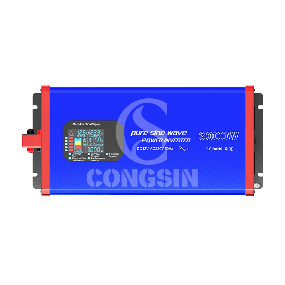
This 3000W full-power pure sine wave inverter (Model: CS3000PSW) adopts pure sine wave output technology (waveform distortion rate <2%), and the output power is highly consistent with mains power quality. It can safely drive high-power precision loads such as air conditioners, refrigerators, medical instruments, and small industrial equipment, avoiding equipment malfunctions or shortened service life caused by unstable waveforms. The device supports DC 12V input (compatible with 10.5V-14.8V wide voltage), continuously outputs 3000W full power, and has a peak power of 6000W, easily coping with the instantaneous startup impact of high-power devices; it is equipped with 4 AC universal sockets (max current 16A) + 2 USB 3.0 fast-charging ports (22.5W per port) to meet the simultaneous power supply needs of multiple devices. Built-in six-fold safety protection (overload, overvoltage, undervoltage, short circuit, overtemperature, reverse connection), combined with dual intelligent silent cooling fans (noise ≤45dB), it achieves the triple advantages of "high power + high safety + low noise," suitable for home emergency, outdoor engineering, vehicle-mounted power supply, small industrial scenarios and other fields.
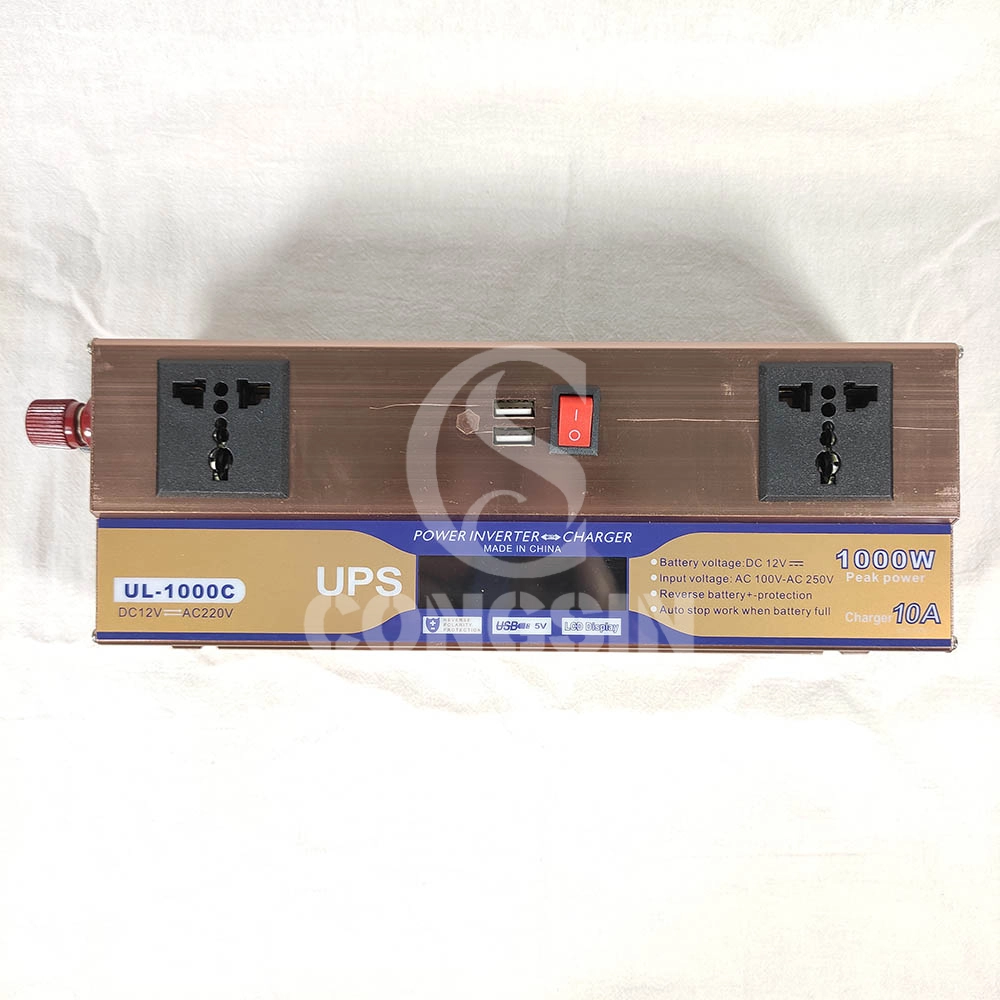
This 1000W modified sine wave inverter has UPS charging function, with DC12V input and AC220V output, and 600W rated power. Equipped with dual universal sockets, two USB ports, an LCD display, and a battery clip, it is professionally designed and has stable performance. It can provide stable AC power conversion and UPS emergency power supply for computers, small home appliances, electronic devices, etc. in home emergency, office, outdoor and other scenarios, meeting the needs of simultaneous power supply and emergency power supply for multiple devices.

This 1500W pure sine wave inverter converts DC 12V to AC 220V power, with a rated power of 1500W and a peak power of 3000W. Equipped with dual fans, LCD display, QC3.0 and PD Type-C fast charging ports, and remote control capability for stable and intelligent power output.

Our CS2000BIG 2000W modified sine wave inverter is a high-power power conversion device that converts DC 12V from batteries into AC 220V electricity. It is designed for heavy-duty use, featuring 2 AC sockets to power multiple high-power devices simultaneously, 2 cooling fans for efficient heat dissipation, and battery terminal wire for stable connection. With its robust construction and large capacity, it is an ideal solution for powering tools, appliances, and equipment in various scenarios, from industrial use to home emergencies.
Get in Touch with Our Team
You can also communicate with us directly through our online contact form. Please fill in the following information, and our team will contact you as soon as possible after receiving your message.

CONGSIN is a trusted OEM factory for power inverters, solar charge controllers, and DC converters. Reliable solutions for global B2B buyers.
 High Quality
 7/24 Service
 Guaranteed Warranty
© 2025 Congsin. All Rights Reserved.
 WeChat
 Scan QR Code
sin cong
teaimei10
Whatsapp: +8618028086791
Scan QR Code