



Pure Sine Wave Inverter with MPPT Charger: Integrated System Architecture
- Introduction
- 1. Define the Pure Sine Wave Inverter–MPPT–Battery Architecture
- 2. Match the PV-to-Battery Charging Envelope
- 3. Coordinate Battery, BMS and Inverter Requirements
- 4. Qualify and Lock the Exact System Configuration
- 5. Turn the Qualified Architecture Into a B2B RFQ
- FAQ
- Request an Inverter–MPPT–Battery Configuration Review
Quick Answer
A pure sine wave inverter with MPPT charger should be qualified as a complete PV-to-battery-to-AC architecture rather than by inverter wattage alone. The MPPT stage must operate within the proposed PV input envelope and the battery charging limits, while the battery must also support the inverter’s sustained and temporary DC demand.
If BMS communication, AC battery charging, transfer behavior or monitoring is required, those functions should be confirmed separately for the proposed product and battery combination.
For B2B procurement, the approval target should therefore include the inverter model, PV/MPPT envelope, battery interface, AC market version, required communication, optional functions and supporting technical documentation.
Introduction
A pure sine wave inverter with MPPT charger connects several electrical functions that are often discussed separately.
Solar energy enters through the PV side. An MPPT charging stage regulates the energy delivered to the battery. The battery stores that energy and later supplies DC power to the inverter. The inverter converts that DC power into AC output for the approved loads.
If any one of these interfaces is mismatched, the overall system may be unsuitable even when the individual products appear acceptable on their own.
This matters especially in B2B projects. A distributor may need one repeatable configuration for a regional market. A system integrator may need to coordinate a particular solar array and battery platform. An OEM/private-label buyer may need a controlled DC version, AC output, charging architecture and documentation set. A professional project buyer may need to compare several supplier proposals against the same system requirement.
System Architecture → PV-to-Battery Charging Envelope → Battery/BMS/Inverter Coordination → System Qualification → B2B RFQ
This page does not size a complete off-grid solar system or replace a dedicated MPPT charge-controller selection guide. It focuses on qualifying the PV–MPPT–battery/BMS–inverter interfaces before a specific B2B system is approved.
That boundary is important because the objective is not to repeat general MPPT theory, battery sizing or off-grid system design. The objective is to determine whether the proposed components and interfaces can operate together as one controlled architecture.
1. Define the Pure Sine Wave Inverter–MPPT–Battery Architecture
Before selecting a model, the project should define how energy is expected to move through the system.
PV Array → MPPT Charging Stage → Battery / BMS → Pure Sine Wave Inverter → AC Loads

Each stage has a different responsibility.
The PV array supplies variable DC energy. The MPPT charging stage operates within the accepted PV input range and converts available solar energy into a charging output suitable for the battery. The battery stores energy and provides DC power to the inverter. The pure sine wave inverter converts that battery-side DC power into AC output for the loads.
Additional functions may also be required, including AC battery charging, source transfer, monitoring, communication and protection. Those functions should be treated as separate system requirements rather than assumed from the phrase “inverter with MPPT charger.”
| System Stage | Main Responsibility |
|---|---|
| PV Array | Supplies solar DC power |
| MPPT Charging Stage | Operates within the PV input envelope and regulates battery charging |
| Battery / BMS | Stores energy and defines battery-side electrical and operating limits |
| Pure Sine Wave Inverter | Converts battery DC power into AC output |
| AC Charger, if required | Charges the battery from an external AC source |
| Transfer Function, if required | Manages source transition where required |
| Monitoring / Communication | Provides data or control where supported by the proposed system |
An MPPT solar charger is not the same function as an AC inverter charger.
MPPT solar charging regulates energy from the PV source to the battery. An AC battery charger uses an external AC source to charge the battery.
A system may provide both functions, only one of them, or neither as an integrated feature. They should therefore be confirmed independently.
The same principle applies to transfer behavior. Pure sine wave output describes the inverter’s AC waveform. It does not, by itself, confirm automatic transfer or UPS-oriented behavior.
Integrated and Modular Architecture
The architecture may use an integrated inverter and MPPT stage or separate devices.
An integrated approach may simplify coordination when one product fits the proposed PV input, battery requirements and AC load. A modular approach can be useful when the solar charging stage needs to be selected independently or when the PV and battery architecture require more flexibility.
Neither approach is universally superior. The engineering question is whether the selected architecture provides compatible and documented interfaces between the PV source, charging stage, battery and AC load.
| Project Architecture | Product Direction | Exact Qualification Still Required |
|---|---|---|
| Inverter + separate MPPT | Pure sine wave inverter + MPPT controller | DC compatibility, PV envelope and battery charging limits |
| Integrated inverter + MPPT | MPPT-integrated or hybrid configuration | PV limits, charging limits, AC output and battery interface |
| Backup-oriented system | Inverter plus charging or transfer where required | Charger and transfer behavior |
| OEM / regional configuration | Qualified base architecture plus customization | AC/DC version, interfaces, market and documentation |
This matrix is not a final product recommendation. It converts the system architecture into a product direction so that the next qualification stage can focus on the correct type of equipment.
A pure sine wave inverter with MPPT charger should be qualified as a complete energy architecture, not only by inverter wattage.
For early product research, buyers can review the current CONGSIN pure sine wave inverter range and MPPT solar charge controllers.
2. Match the PV-to-Battery Charging Envelope
Once the architecture is defined, the next task is to qualify the charging path from the solar source to the battery.
PV → MPPT → Battery
The MPPT stage sits between two electrical envelopes. On the PV side, the system has voltage, current and operating conditions created by the solar array. On the battery side, the system has charging voltage, charging current and battery operating limits.
The MPPT stage must remain compatible with both.
PV-to-MPPT Interface
The project should first define the proposed solar input. Relevant information can include PV module specification, series/parallel arrangement, operating voltage, open-circuit voltage, input current, total array power and relevant environmental conditions.
The proposed MPPT stage should then be checked against its documented input limits. Depending on the product, these may include PV input voltage, MPPT operating range, maximum PV voltage, allowable input current and accepted PV power.
The important procurement question is not simply whether the product supports MPPT.
Can the proposed array remain within the permitted MPPT input envelope under the expected operating conditions?
This keeps the discussion at system-interface level rather than turning the page into a general MPPT tutorial.
MPPT-to-Battery Interface
The next boundary is the battery. The charging output should be compatible with the selected battery system.
Relevant items include battery voltage, permitted charging voltage, charging current, battery chemistry, battery operating limits and applicable BMS restrictions.
| Interface | What Must Match |
|---|---|
| PV → MPPT | Voltage, current and operating range |
| MPPT → Battery | Charging voltage and charging current |
| Battery | Chemistry, charging limits and operating restrictions |
| System | Required charging power and operating state |
A design can fail if only one side is incompatible. The proposed PV array may fall outside the MPPT input range even if the battery charging output is appropriate. The opposite is also possible: the PV side may be acceptable while the charging output does not match the battery requirements.
The MPPT stage must match both the PV operating envelope and the battery charging limits.
This principle also helps determine whether the project should use an integrated MPPT stage or an external controller.
An integrated stage may be suitable when one system can accept the proposed PV source and charge the selected battery within the required limits. A separate MPPT controller may be more appropriate when the solar charging design must be selected independently from the inverter.
The decision should be based on interface compatibility rather than on a general preference for integrated or external architecture.
For earlier-stage background, the existing MPPT charge controller and hybrid inverter compatibility guide can support general compatibility research.
3. Coordinate Battery, BMS and Inverter Requirements
The battery is the shared interface between the solar charging stage and the inverter.
The MPPT stage charges it. The inverter discharges it. The BMS, where applicable, may impose operating limits and may also communicate with other equipment.
For that reason, battery qualification should not be based on nominal voltage alone.
Charging Compatibility → Discharge Capability → Communication Compatibility
Charging Compatibility
The charging side begins with the battery requirements.
The battery voltage, chemistry and permitted charging conditions should match the output of the proposed MPPT stage. A project should identify the required charging voltage and charging current and determine whether any battery-management restrictions affect those values.
The charging profile should not be generalized across different batteries. If a specific battery platform is planned, its charging requirements should be compared with the proposed solar-charging stage.
Discharge Capability
The same battery must also support the inverter.
Battery energy capacity and battery current capability are not the same thing. A battery can store enough energy for the desired runtime but still require further review if the inverter creates high DC current demand.
Battery → Inverter → AC Loads
The inverter must support the AC load envelope. The battery must support the DC current required by the inverter to deliver that load. Both sustained demand and relevant temporary events should be included.
Battery energy capacity and battery current-delivery capability are separate system constraints.
This means a battery should not be approved only because its Ah or Wh value appears sufficient. The discharge capability must also be appropriate for the proposed inverter and operating state.
The physical DC interface is part of this relationship as well. Conductor sizing, connection length, terminals, isolation, protection and voltage drop may all matter in a real installation.
Final values should be determined from exact equipment documentation and actual project conditions rather than universal assumptions.
BMS Communication
Communication creates a third layer.
A battery can be electrically compatible with an inverter without providing digital communication compatibility.
In the wider market, battery systems may use CAN, RS485 or other protocols. However, the presence of a physical communication port does not prove that two devices support the same protocol or data exchange.
If communication is required, the project should define what function is expected. Examples may include state-of-charge information, charging limits, discharge limits, battery temperature, fault status or other battery-management information.
Those functions require confirmed support between the proposed battery and system.
BMS communication and electrical compatibility are separate requirements.
The project should therefore answer two different questions.
Are the battery voltage, charging limits and discharge capability electrically compatible with the proposed inverter and MPPT stage?
If communication is required, do the proposed devices support the required interface and protocol?
If the communication requirement has not been confirmed, it should remain an open item. It should not be inferred from another model, another battery or the presence of a similar connector.
This gives B2B buyers a much stronger qualification method than a broad statement such as “compatible with lithium batteries.”
A useful battery-interface record should instead identify battery voltage, charging limits, discharge capability, required communication, relevant battery-management requirements and unresolved qualification items.
For selected mobile, RV or remote battery-based projects where solar charging forms part of the architecture, the same interface logic applies.
A battery should not be qualified for an inverter–MPPT system through voltage matching alone. Charging limits, discharge capability and required communication support should be reviewed separately.
4. Qualify and Lock the Exact System Configuration
Once the architecture and interfaces are defined, the project can move from system design to product approval.
System Requirement → Architecture Type → Product Family → System Qualification → Configuration Lock → Validation
Architecture type defines the general solution. Product family narrows the available options. System qualification determines whether the proposed product version actually satisfies the project requirement.
A pure sine wave inverter may be appropriate for one architecture. A separate MPPT controller may provide the charging stage in another. An MPPT-integrated hybrid configuration may be relevant when multiple functions are combined.
These choices identify candidate directions. They do not automatically prove suitability.
| Qualification Area | Confirm for the Proposed System |
|---|---|
| AC Output | Continuous output and relevant temporary capability |
| Battery DC | Battery voltage and discharge capability |
| PV / MPPT | PV voltage, current and operating envelope |
| Battery Charging | Charging voltage and charging-current limits |
| BMS | Communication support where required |
| AC Charging / Transfer | Presence and documented behavior where required |
| Market | AC voltage, frequency and regional version |
| Monitoring | Supported functions where required |
| Documentation | Technical evidence supporting approval |
| OEM Definition | Confirmed project-specific requirements |
Product-family fit is not the same as exact-system qualification.
This distinction matters because products with similar headline specifications can differ in battery voltage, PV input range, MPPT operating range, charging current, AC output, communication, optional charging, transfer behavior, monitoring and regional configuration.
A nominal wattage therefore should not become the final approval criterion.
Configuration Lock
Once the proposed system has been accepted, the final approved configuration should be recorded.
Exact Model + DC Version + AC Version + MPPT/PV Envelope + Battery Interface + Required Communication + Optional Functions + Market Version + Documentation + OEM Definition
This becomes the controlled procurement reference.
If a supplier later proposes a different product version, battery voltage, AC output, MPPT range or communication option, the proposed substitution can be checked against the same system requirement.
This is particularly valuable in distributor, OEM/private-label and repeat-order projects.
Without a configuration lock, a technically approved solution can easily be reduced to a vague commercial description such as “2000W pure sine wave inverter with MPPT.”
That description does not preserve the details that originally made the system acceptable.
Representative Validation
Validation should remain focused on the complete approved system. It does not need to become a separate universal test manual.
A representative validation process should confirm five areas:
- The proposed PV source remains inside the intended MPPT operating envelope.
- Solar charging remains within the approved battery charging limits.
- The inverter and battery support the required sustained and temporary AC load demand.
- The battery provides suitable discharge capability across the intended operating condition.
- Optional functions such as BMS communication, AC charging, transfer or monitoring are verified where required.
The validation target is the complete approved configuration, not the inverter alone.
Broader system-sizing questions can remain with the existing off-grid solar inverter system design guide.
5. Turn the Qualified Architecture Into a B2B RFQ
The final engineering output should become a procurement document that allows suppliers to return comparable technical proposals.
A request such as “Need a 2000W pure sine wave inverter with MPPT” can start a conversation, but it is not sufficient for final approval.
It does not define the PV source, battery interface, charging limits, communication requirements, AC market version or required optional functions.
| RFQ Area | Buyer Input |
|---|---|
| Application / Loads | Continuous AC load and relevant temporary demand |
| PV | Array or string configuration |
| Battery | Voltage, chemistry, capacity and known charge/discharge limits |
| Architecture | Integrated MPPT or external controller requirement |
| Communication | Required BMS or monitoring support |
| AC / Backup | Voltage, frequency and charging/transfer requirement |
| Market | Destination country or region |
| Project | Quantity, OEM/private-label and documentation requirements |
The supplier should then return the proposed system with enough technical detail for approval.
The response should confirm the model and version, DC input, AC output, PV and MPPT limits, charging capability, battery interface and applicable communication support.
If AC charging is required, that function should be confirmed explicitly. If transfer or UPS-oriented behavior is required, the supplier should confirm the documented behavior for the proposed system. If monitoring is required, the interface and supported function should be stated rather than assumed.
The supplier response should also include the technical documentation needed for project approval.
This makes the RFQ a bridge between engineering and procurement rather than only a request for price.
For distributors, it helps establish repeatable market configurations. For integrators, it connects the design requirement with the equipment proposal. For OEM/private-label buyers, it defines the product version that should remain consistent through approval and future orders.
CONGSIN Project Fit
CONGSIN currently lists DC-to-AC power inverters, portable power stations and solar charge controllers among its core product areas. The company also supports OEM/ODM, private labeling, distribution and bespoke customization discussions.
These areas allow CONGSIN to participate in inverter, solar-charging and battery-based project discussions.
However, product-specific functions such as MPPT limits, charging current, BMS communication, AC charging, transfer behavior, monitoring and protection should still be confirmed for the proposed product rather than generalized across the full range.
For product research, buyers can review the Pure Sine Wave Inverter range and MPPT Solar Charge Controllers.
FAQ
What is a pure sine wave inverter with MPPT charger?
It is a product or system architecture that combines pure sine wave DC-to-AC conversion with MPPT-regulated solar charging. The phrase alone does not define the exact PV input range, charging current, battery compatibility, communication, AC charging or transfer functions, so these should be confirmed for the proposed configuration.
When should an integrated MPPT architecture be used?
An integrated architecture can be suitable when one product or system matches the PV input, battery charging requirements and AC load needs of the project. A separate MPPT controller may be preferable when the solar charging stage needs to be selected or expanded independently.
How should MPPT charging be matched to a battery?
The proposed PV configuration should remain inside the MPPT input envelope, while the charging output should remain within the battery’s permitted voltage and current limits. Battery chemistry and applicable BMS restrictions should also be reviewed.
Does electrical compatibility guarantee BMS communication?
No. A battery can be electrically compatible with an inverter while digital BMS communication is not supported between the proposed devices. If communication is required, the interface and protocol should be verified separately.
Does an MPPT inverter automatically include AC charging or transfer?
No. MPPT solar charging, AC battery charging and automatic transfer are separate functions. A system may provide one or more of them, but each required function should be confirmed for the proposed model or system.
What should a B2B RFQ include for a pure sine wave inverter with MPPT charger?
It should define the AC load, PV configuration, battery voltage and chemistry, charging requirements, communication needs, AC voltage and frequency, optional charging or transfer functions, destination market, quantity and OEM or documentation requirements.
Request an Inverter–MPPT–Battery Configuration Review
For a project discussion, prepare the PV configuration, battery architecture, AC load requirement, destination market, expected quantity and any charging, transfer or communication functions required by the project.


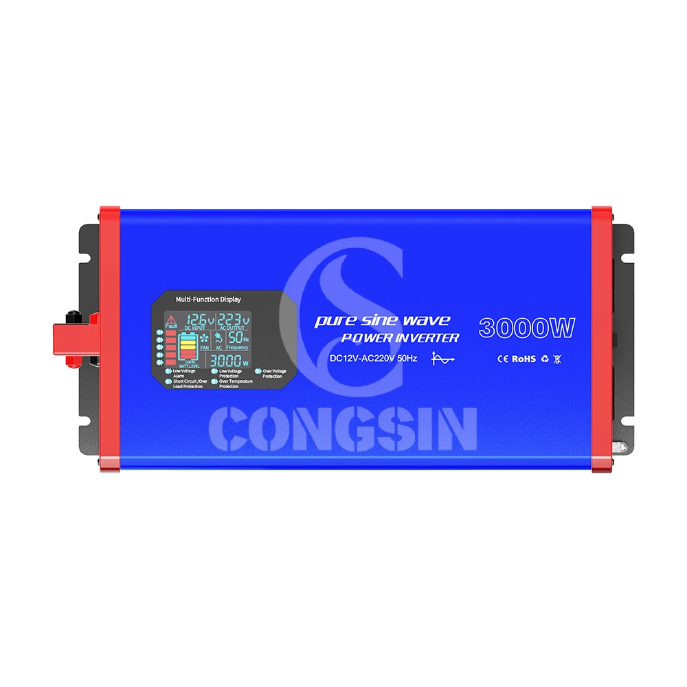
This 3000W full-power pure sine wave inverter (Model: CS3000PSW) adopts pure sine wave output technology (waveform distortion rate <2%), and the output power is highly consistent with mains power quality. It can safely drive high-power precision loads such as air conditioners, refrigerators, medical instruments, and small industrial equipment, avoiding equipment malfunctions or shortened service life caused by unstable waveforms. The device supports DC 12V input (compatible with 10.5V-14.8V wide voltage), continuously outputs 3000W full power, and has a peak power of 6000W, easily coping with the instantaneous startup impact of high-power devices; it is equipped with 4 AC universal sockets (max current 16A) + 2 USB 3.0 fast-charging ports (22.5W per port) to meet the simultaneous power supply needs of multiple devices. Built-in six-fold safety protection (overload, overvoltage, undervoltage, short circuit, overtemperature, reverse connection), combined with dual intelligent silent cooling fans (noise ≤45dB), it achieves the triple advantages of "high power + high safety + low noise," suitable for home emergency, outdoor engineering, vehicle-mounted power supply, small industrial scenarios and other fields.
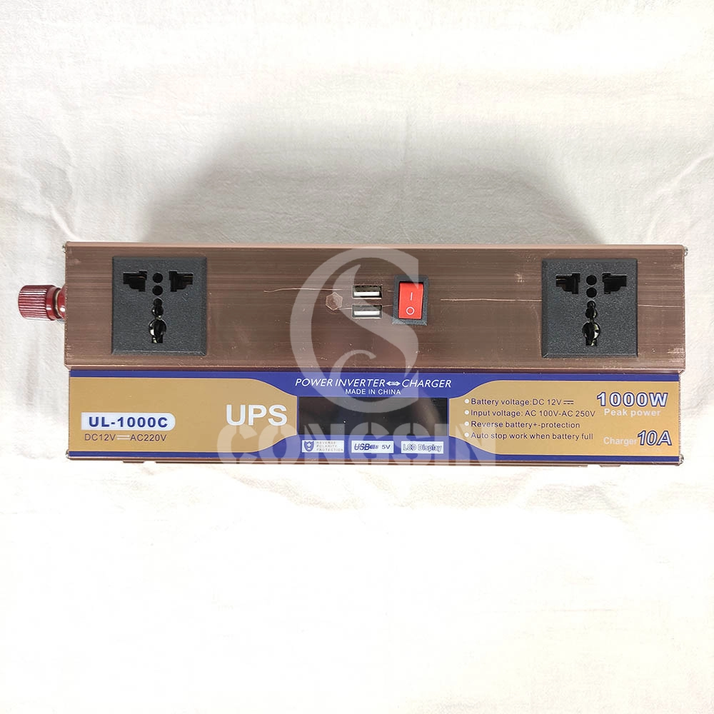
This 1000W modified sine wave inverter has UPS charging function, with DC12V input and AC220V output, and 600W rated power. Equipped with dual universal sockets, two USB ports, an LCD display, and a battery clip, it is professionally designed and has stable performance. It can provide stable AC power conversion and UPS emergency power supply for computers, small home appliances, electronic devices, etc. in home emergency, office, outdoor and other scenarios, meeting the needs of simultaneous power supply and emergency power supply for multiple devices.

This 1500W pure sine wave inverter converts DC 12V to AC 220V power, with a rated power of 1500W and a peak power of 3000W. Equipped with dual fans, LCD display, QC3.0 and PD Type-C fast charging ports, and remote control capability for stable and intelligent power output.

Our CS2000BIG 2000W modified sine wave inverter is a high-power power conversion device that converts DC 12V from batteries into AC 220V electricity. It is designed for heavy-duty use, featuring 2 AC sockets to power multiple high-power devices simultaneously, 2 cooling fans for efficient heat dissipation, and battery terminal wire for stable connection. With its robust construction and large capacity, it is an ideal solution for powering tools, appliances, and equipment in various scenarios, from industrial use to home emergencies.
Get in Touch with Our Team
You can also communicate with us directly through our online contact form. Please fill in the following information, and our team will contact you as soon as possible after receiving your message.

CONGSIN is a trusted OEM factory for power inverters, solar charge controllers, and DC converters. Reliable solutions for global B2B buyers.
 High Quality
 7/24 Service
 Guaranteed Warranty
© 2025 Congsin. All Rights Reserved.
 WeChat
 Scan QR Code
sin cong
teaimei10
Whatsapp: +8618028086791
Scan QR Code