



Storage Planning for Off-Grid Loads: Daily Energy, Autonomy and Battery Reserve
- Introduction
- 1. Establish the Daily Energy Budget From the Operating Timeline
- 2. Define Autonomy as a Project Operating Scenario
- 3. Allocate Usable Storage Without Double-Counting Reserve
- 4. Verify Recovery Before the Next Operating Cycle
- 5. Convert the Storage Plan Into a Controlled B2B RFQ
- FAQ
- Request an Off-Grid Storage Requirement Review
Quick Answer
Off-grid inverter battery sizing starts by defining the loads that must remain supplied during a no-charge operating period, the energy that must remain protected, and the battery state that must be restored before the next cycle.
A defensible storage plan has five outputs: an approved daily load schedule, a defined no-charge autonomy period, a retained-load policy, a protected-reserve boundary, and a recovery target.
The purpose is not simply to calculate nominal battery watt-hours or amp-hours. It is to establish how much usable energy the project must make available, which portion planned operation must leave unused, and whether the charging system can restore the required state in time.
These requirements form the basis for subsequent battery, inverter and charging-equipment qualification.
Introduction
An off-grid storage requirement cannot be determined from inverter wattage alone. Inverter power establishes what the equipment must support at a particular moment; stored energy determines how long approved loads can be supplied.
For a B2B project, the starting question is what the system must accomplish over time.
A distributor may need a repeatable way to discuss operating duration without attaching one universal runtime claim to a product. An integrator needs an energy requirement traceable to operating conditions. A transportation or outdoor partner may need to plan around uncertain charging opportunities. A professional or commercial user may require essential loads to remain supplied after less important equipment has been disconnected.
These requirements cannot be captured by a battery-capacity figure without its operating assumptions.
This guide begins with the operating scenario rather than a product configuration. It defines which loads must be supplied, under which no-charge conditions, how available battery energy is allocated, and what must be restored before the next operating cycle.
It assumes that the basic inverter-load and battery-capacity calculation methods are understood. Detailed Wh-to-Ah conversion, battery-bank arrangement, discharge-current sizing and battery configuration belong in the dedicated battery bank sizing guide.
The engineering objective of this page is:
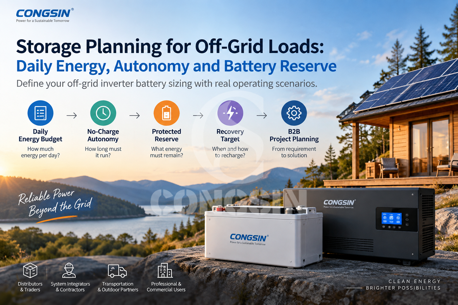
Approved load timeline → No-charge operating requirement → Protected reserve → Usable-energy requirement → Recovery target
That sequence allows a buyer to define a storage operating requirement before deciding which exact inverter, battery or charging components could satisfy it.
1. Establish the Daily Energy Budget From the Operating Timeline
The first deliverable is a 24-hour energy budget based on the way the loads actually operate.
A list of connected devices is not enough. The buyer must distinguish continuously operating equipment from scheduled, intermittent and deferrable loads. The schedule should also identify which loads must remain supplied when dependable charging becomes unavailable.
For a constant-power load, the basic energy relationship is:
Energy (Wh) = Power (W) × Operating time (h)
For multiple loads, daily energy is the sum of their individual energy demands over the approved schedule.
Build a 24-Hour Load Profile
Hypothetical example: All values in the following calculation are illustrative planning assumptions—not CONGSIN product measurements, customer project data, recommended system specifications or runtime guarantees.
| Hypothetical load | Running power | Daily operation | Daily AC energy | Priority |
|---|---|---|---|---|
| Communications and monitoring | 100 W | 24 h | 2,400 Wh | Essential |
| Lighting | 40 W | 5 h | 200 Wh | Essential |
| Intermittent refrigeration | 100 W | 8 h equivalent | 800 Wh | Essential |
| Deferrable equipment | 200 W | 2 h | 400 Wh | Deferrable |
| Normal daily total | — | — | 3,800 Wh | — |
The refrigeration entry uses an equivalent operating duration rather than assuming uninterrupted operation for eight hours. A real project should use measured energy consumption or a supportable duty-cycle estimate.
The normal daily AC load energy is:
2,400 Wh/day + 200 Wh/day + 800 Wh/day + 400 Wh/day = 3,800 Wh/day
The table provides two outputs. The first is the normal energy requirement of 3,800 Wh/day. The second is the distinction between loads that must continue during an interruption and loads the project may permit to stop.
That distinction becomes important when the no-charge operating requirement is defined.
Running and startup power must still be checked separately. A sufficient daily Wh budget does not establish that the inverter can support simultaneous or temporary electrical demand. For that preceding task, use the inverter load worksheet.
Stage 1 output: an approved daily energy budget with operating durations, load priorities and clearly identified measured or estimated inputs.
2. Define Autonomy as a Project Operating Scenario
Daily energy describes the normal schedule. Autonomy describes what the system must accomplish when dependable charging is unavailable.
A statement such as “two days of autonomy” remains incomplete until the project defines the starting condition, retained loads, permitted load reduction and stopping condition.
Two systems with the same normal daily energy may require different storage capacities if one must retain every load while the other can disconnect deferrable equipment.
Define the No-Charge Window and Retained Loads
The buyer should establish a no-charge operating scenario before calculating its energy requirement.
| Scenario | Load policy | Charging assumption | Planning output |
|---|---|---|---|
| Normal operation | Full approved daily schedule | Actual project conditions | Normal daily energy |
| Required no-charge autonomy | Approved retained loads | No dependable charging contribution | Autonomy energy |
| Extended interruption, if required | Separately approved reduced-load schedule | Defined conservative condition | Additional or alternative operating requirement |
An extended-interruption schedule may replace the normal schedule rather than being added to it. The calculation should follow the actual sequence of operation.
The recovery period is not part of the no-charge autonomy scenario. Recovery is checked separately after the required stored energy has been established.
In the hypothetical example, the project permits the 400 Wh/day deferrable load to be disconnected.
The retained daily AC energy becomes:
3,800 Wh/day − 400 Wh/day = 3,400 Wh/day
Assume, solely for this example, that the project requires these retained loads to operate for 48 hours without dependable charging.
The required AC load energy is:
3,400 Wh/day × 2 days = 6,800 Wh AC
The 48-hour period is an illustrative project requirement, not a standard autonomy target or a CONGSIN performance commitment.
The 6,800 Wh result is also a load-side energy requirement. It does not yet account for the modeled energy drawn from the battery or the protected reserve.
Establish the Operating Boundaries
Before approving the autonomy scenario, the buyer should document the assumed starting battery condition, exact no-charge duration, retained loads, permitted load reduction, planned stopping condition and any charging contribution that can genuinely be treated as dependable.
If a scenario is expressly defined as having no reliable charging, unconfirmed solar generation should not be used to reduce its storage requirement.
This does not mean solar, AC or vehicle charging is irrelevant. It means charging belongs in the later recovery assessment rather than being silently included in a no-charge calculation.
Stage 2 output: an approved autonomy scenario with 6,800 Wh of hypothetical AC load demand over 48 hours, plus explicit starting, operating and stopping conditions.
3. Allocate Usable Storage Without Double-Counting Reserve
The next step is to translate the AC load requirement into the battery-side energy that must be available while maintaining the project’s protected reserve.
This is the principal distinction between storage operating-requirement planning and a general battery-capacity calculation.
The buyer is not yet selecting a battery model. The buyer is defining how available energy must be allocated and what portion must remain protected at the end of planned operation.
Build a Consistent Energy Ledger
The energy ledger needs to separate four elements.
| Element | Meaning | Accounting treatment |
|---|---|---|
| Autonomy load energy | Energy required by retained loads | Derived from the approved no-charge schedule |
| Conversion and operating losses | Difference between load-side delivery and battery-side consumption | Use a defined loss model; do not add the same loss twice |
| Protected operating reserve | Energy planned operation must leave unused | Keep separate from autonomy consumption |
| Technical operating window | Energy the battery is permitted to make available under stated conditions | Confirm whether the reserve is inside that window or already reflected in its definition |
Temperature, aging and load uncertainty may also matter. An adjustment should be added only when its purpose is defined and the same effect has not already been incorporated into another factor.
Continue the Hypothetical Example
All numerical factors below are hypothetical. The assumed 85% net AC-delivery factor, 2,000 Wh reserve, 80% technical operating window and resulting 12.5 kWh nominal energy are not universal sizing standards, CONGSIN specifications or approved project configurations.
Assumption 1 — Net AC-delivery factor: 85%. For this example, assume a net AC-delivery factor of 85% for converting modeled battery-side energy consumption into delivered AC load energy. This is one illustrative aggregate loss assumption for the stated operating schedule. A real project must use an appropriate equipment- and load-specific basis.
The same losses must not then be added again as separate conversion or standby allowances if they are already included in the selected net factor.
Battery-side energy required to deliver 6,800 Wh AC:
6,800 Wh ÷ 0.85 = 8,000 Wh battery-side
Assumption 2 — Protected operating reserve: 2,000 Wh. Assume the hypothetical project requires 2,000 Wh of battery-side energy to remain protected at the planned stopping point. This reserve has not been included in the 8,000 Wh expected to be consumed by the loads.
8,000 Wh + 2,000 Wh = 10,000 Wh
The result is the energy that must be available within the defined battery operating window: 8,000 Wh for the modeled load and 2,000 Wh to remain protected.
Assumption 3 — Technical operating window: 80% of nominal energy. Starting-condition assumption: This hypothetical example begins at the defined upper boundary of the battery’s assumed technical operating window. The 80% factor represents the energy available from that starting condition to the technical lower boundary. It does not mean that 80% of nominal energy remains available from any arbitrary initial state of charge.
The project’s assumed 2,000 Wh protected reserve is held inside that otherwise available 80% technical window. It is not energy below the technical cutoff, and it has not already been included in the 8,000 Wh load requirement.
Under these specific assumptions:
10,000 Wh ÷ 0.80 = 12,500 Wh nominal
The complete hypothetical calculation is:
| Calculation stage | Illustrative result |
|---|---|
| Normal daily AC energy | 3,800 Wh/day |
| Retained daily AC energy | 3,400 Wh/day |
| AC demand over 48 hours | 6,800 Wh |
| Battery-side demand using assumed 85% net delivery factor | 8,000 Wh |
| Available energy required, including assumed 2,000 Wh protected reserve | 10,000 Wh |
| Nominal energy using assumed 80% technical operating window | 12,500 Wh |
Hypothetical result only: 12.5 kWh is a mathematical illustration under the stated assumptions. It is not a recommended battery capacity, verified runtime or approved CONGSIN system configuration.
This example produces a nominal-energy figure only because its hypothetical starting condition, loss factor, reserve and technical operating window have all been defined.
It does not establish the correct battery voltage, chemistry, capacity arrangement, discharge capability or actual deliverable energy for a real project. Those decisions require a separate equipment qualification process.
Define Reserve Without Counting It Twice
An allowable depth of discharge and a project reserve can both be appropriate when they represent different boundaries.
A technical operating window may define the energy available before reaching a battery’s permitted lower boundary. The project may require planned operation to stop earlier, leaving a protected portion of that otherwise available energy unused.
In that case, the technical window and project reserve have distinct roles. Double-counting occurs when the project’s stated operating window already includes the protected reserve, but the same reserve is added or subtracted again.
The same principle applies to temperature, aging and uncertainty allowances: the buyer should identify what each adjustment represents and whether the underlying capacity or performance value already includes that effect.
The governing rule is not “always add another margin.” It is “define every energy boundary once and account for each distinct requirement once.”
This guide therefore stops at the approved energy-allocation requirement. Battery-capacity conversion, discharge-current sizing, BMS protection and physical configuration should be developed through the dedicated battery bank sizing guide and the exact equipment documentation.
Stage 3 output: the energy required within the defined technical window, the protected reserve that must remain, and a documented basis for subsequent battery qualification.
4. Verify Recovery Before the Next Operating Cycle
Completing one no-charge period does not establish that a storage configuration can support a repeated operating schedule.
The next question is:
Can the charging system restore the required battery state before the next approved cycle begins?
That recovery requirement must be defined separately from autonomy.
Establish the Recovery Target
In the hypothetical example, the modeled autonomy period consumed 8,000 Wh of battery-side energy while leaving the assumed 2,000 Wh reserve protected.
To return to the same starting condition, the system would need to replenish the energy actually removed, subject to real battery-charging behavior and charging-system losses.
The 8,000 Wh figure is therefore the example’s modeled battery-side energy depletion. It is not a specification for the energy that must enter a charger, and it is not a charger-power rating.
The buyer must still confirm the available charging sources, charging window, loads operating during recovery, battery charging limits and relevant environmental restrictions.
A system may have enough stored energy for a single interruption but fail repeated operation if the required energy cannot be restored before the next cycle.
Solar charging may be available during normal operation but unreliable during the defined autonomy event. AC or vehicle charging may be possible in some applications but absent in others.
None of those sources should be credited to the recovery plan until the project confirms that the source is installed, available and suitable for the required recovery condition.
Keep Exact Equipment Qualification as a Separate Approval
The approved energy plan provides inputs to equipment review; it does not replace that review.
Subsequent qualification must establish whether the proposed inverter and battery can deliver the required load under actual conditions. This includes the appropriate DC and AC versions, battery voltage and chemistry, discharge capability, BMS protections, relevant efficiency and self-consumption data, and environmental limits.
Stored-energy sufficiency and electrical delivery capability are separate approval checks.
The project should also state how success will be demonstrated: starting condition, retained-load schedule, operating duration, planned stopping point, protected reserve and recovery target.
Detailed electrical configuration belongs in the battery bank sizing guide. For a runtime check based on already selected equipment, use the complementary inverter battery runtime guide.
Stage 4 output: an approved recovery condition and a concise list of equipment interfaces requiring verification—not an unverified charger rating or promised system runtime.
5. Convert the Storage Plan Into a Controlled B2B RFQ
The procurement value of this process is that suppliers can respond to the same approved operating requirement instead of interpreting a vague request such as “a battery for a 2,000 W inverter.”
For this article, the RFQ should carry five principal engineering deliverables.
| Required deliverable | Information to include |
|---|---|
| Approved Load Scenario | Daily timeline, normal and retained loads, deferrable-load policy, measurement or estimate basis |
| No-Charge Autonomy | Required duration, assumed starting condition, permitted charging contribution and operating outcome |
| Protected Reserve Rule | Technical operating window, planned stop condition, reserve definition and distinct allowances |
| Recovery Target | State to be restored, deadline for recovery, available charging sources and concurrent loads |
| Pending Equipment Interfaces | Existing or proposed equipment, functional responsibilities and electrical or performance items requiring verification |
This is intentionally narrower than a complete battery procurement specification. The five deliverables establish what the system must accomplish before suppliers finalize what equipment could accomplish it.
Destination market, anticipated quantity, documentation and OEM/private-label needs can accompany the request as commercial context. They should not substitute for the operating requirement.
A supplier response should identify:
Proposed Equipment List + Functional Responsibilities + Interfaces Requiring Verification
This does not imply that a complete compatible system has already been approved.
For distributors, the documented requirement supports consistent configuration discussions without promising the same runtime for every customer. For integrators, it provides a basis for interface and substitution review. Transportation and outdoor partners can make charging uncertainty explicit. Professional and commercial customers can connect retained loads and reserve rules to a measurable operating outcome.
CONGSIN supports OEM/ODM, private-label, distribution and bespoke customization discussions. However, a proposed inverter, battery and charging arrangement must still be qualified for the actual requirement; the existence of those services does not establish compatibility or guarantee a particular autonomy period.
Buyers considering an inverter-only configuration can review the CONGSIN pure sine wave inverter range as a product direction. Product selection should follow—not replace—the approved storage operating requirement.
Final engineering deliverable:
Load Timeline + No-Charge Autonomy + Protected Reserve + Recovery Target + Pending Equipment Verification
FAQ
How should buyers define autonomy when off-grid charging is uncertain?
Define autonomy as an explicit operating period with an approved starting condition, retained-load schedule and planned stopping point. If solar or another charging source is not dependable during that period, do not assume it will reduce the required stored energy. Evaluate charging separately when establishing how the system must recover before the next operating cycle.
Which loads should remain in the no-charge energy budget?
The project owner should identify which loads must continue, which may be reduced and which may be delayed or disconnected. The no-charge budget should reflect the approved retained-load schedule rather than automatically including every normal-use load or excluding loads without authorization. Load priority is a project requirement, not a universal equipment classification.
How is protected reserve different from the battery’s technical operating window?
The technical operating window defines energy available under the battery’s stated starting condition and operating limits. Protected reserve is energy the project requires to remain unused at its planned operating stop. A project may hold reserve within the technically available window, but the exact relationship must be defined. No single reserve amount, SOC percentage or usable-capacity factor should be assumed for every battery or application.
How can DoD and reserve allowances be applied without double-counting?
Define the purpose of each adjustment before applying it. An allowable DoD or operating-window limit may establish technically available energy, while a separate reserve may require planned operation to stop earlier. Both can be appropriate when they represent distinct boundaries. If the operating-window definition already includes the protected reserve, adding that same reserve again would double-count it. Numerical examples must state their assumptions explicitly.
What must be confirmed before an off-grid storage requirement can be approved?
Confirm the load timeline, retained loads, no-charge duration, starting condition, protected-reserve rule and required recovery state. The proposed inverter, battery and charging equipment must then be checked against those requirements using applicable model-specific and project data. A hypothetical calculation alone cannot establish an approved battery configuration, guaranteed runtime or complete-system compatibility.
Request an Off-Grid Storage Requirement Review
Share your load timeline, retained loads, required no-charge period, protected-reserve rule, existing equipment, available charging sources and recovery target.
These inputs provide a basis for discussing the proposed inverter direction, equipment responsibilities and interfaces that require confirmation before a storage configuration can be approved.


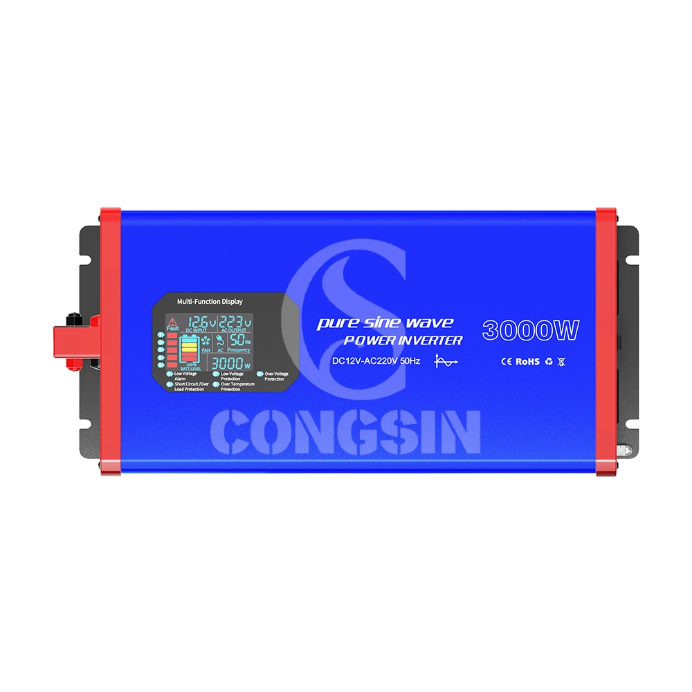
This 3000W full-power pure sine wave inverter (Model: CS3000PSW) adopts pure sine wave output technology (waveform distortion rate <2%), and the output power is highly consistent with mains power quality. It can safely drive high-power precision loads such as air conditioners, refrigerators, medical instruments, and small industrial equipment, avoiding equipment malfunctions or shortened service life caused by unstable waveforms. The device supports DC 12V input (compatible with 10.5V-14.8V wide voltage), continuously outputs 3000W full power, and has a peak power of 6000W, easily coping with the instantaneous startup impact of high-power devices; it is equipped with 4 AC universal sockets (max current 16A) + 2 USB 3.0 fast-charging ports (22.5W per port) to meet the simultaneous power supply needs of multiple devices. Built-in six-fold safety protection (overload, overvoltage, undervoltage, short circuit, overtemperature, reverse connection), combined with dual intelligent silent cooling fans (noise ≤45dB), it achieves the triple advantages of "high power + high safety + low noise," suitable for home emergency, outdoor engineering, vehicle-mounted power supply, small industrial scenarios and other fields.
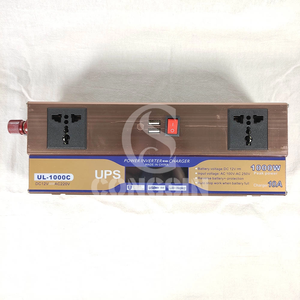
This 1000W modified sine wave inverter has UPS charging function, with DC12V input and AC220V output, and 600W rated power. Equipped with dual universal sockets, two USB ports, an LCD display, and a battery clip, it is professionally designed and has stable performance. It can provide stable AC power conversion and UPS emergency power supply for computers, small home appliances, electronic devices, etc. in home emergency, office, outdoor and other scenarios, meeting the needs of simultaneous power supply and emergency power supply for multiple devices.

This 1500W pure sine wave inverter converts DC 12V to AC 220V power, with a rated power of 1500W and a peak power of 3000W. Equipped with dual fans, LCD display, QC3.0 and PD Type-C fast charging ports, and remote control capability for stable and intelligent power output.

Our CS2000BIG 2000W modified sine wave inverter is a high-power power conversion device that converts DC 12V from batteries into AC 220V electricity. It is designed for heavy-duty use, featuring 2 AC sockets to power multiple high-power devices simultaneously, 2 cooling fans for efficient heat dissipation, and battery terminal wire for stable connection. With its robust construction and large capacity, it is an ideal solution for powering tools, appliances, and equipment in various scenarios, from industrial use to home emergencies.
Get in Touch with Our Team
You can also communicate with us directly through our online contact form. Please fill in the following information, and our team will contact you as soon as possible after receiving your message.

CONGSIN is a trusted OEM factory for power inverters, solar charge controllers, and DC converters. Reliable solutions for global B2B buyers.
 High Quality
 7/24 Service
 Guaranteed Warranty
© 2025 Congsin. All Rights Reserved.
 WeChat
 Scan QR Code
sin cong
teaimei10
Whatsapp: +8618028086791
Scan QR Code