



OEM Pure Sine Wave Inverter Development Roadmap: Electrical Specifications, Housing, Ports and Branding
- Quick Answer
- 1. Establish the OEM Program Baseline and Initial Feasibility Scope
- 2. Stabilize the Electrical Architecture Before Finalizing the Physical Configuration
- 3. Co-develop Housing, Thermal Architecture and External Interfaces
- 4. Lock Branding, Product Identity and Documentation
- 5. Validate the Engineering Sample and Close Deviations
- 6. Release the Final Production Quote and Order Handover
- Frequently Asked Questions
- Start an OEM Pure Sine Wave Inverter Project Review
Quick Answer
An OEM pure sine wave inverter project should be managed as a controlled product-development program rather than as a collection of separate customization requests.
The project can begin with an initial brief and a feasibility or budgetary quotation before every engineering detail is finalized. That early commercial discussion helps determine whether the proposed platform, customization depth and project direction are realistic enough to continue. It should not, however, be confused with the final commercial basis for repeat production.
Once the project moves forward, electrical, mechanical, thermal and interface development should be coordinated together. They may iterate in parallel, but the physical product should not be finalized until the main electrical architecture, operating boundaries and interface requirements are sufficiently stable. Branding and documentation can then be locked to the controlled configuration, followed by engineering-sample validation, deviation closure and approval of the production baseline.
Initial Project Brief and Feasibility Quote → Program Baseline → Electrical, Mechanical and Interface Co-design → Branding and Documentation Lock → Engineering Sample → Deviation Closure → Production Baseline → Final Production Quote and Order Handover
A production quotation may be issued earlier, but it should be updated or reconfirmed after the product configuration and production baseline are approved.
This article begins after the buyer has already selected pure sine wave inversion as the appropriate product direction. It does not repeat basic waveform education, generic inverter sizing or unverified assumptions about fixed MOQ, lead time, certification coverage, communication ports or customization capability. Those items must be confirmed against the actual project and proposed inverter platform.
| Development Gate | Approval Question | Controlled Output |
|---|---|---|
| Initial feasibility | Is the project direction viable? | Initial scope and quotation basis |
| Program baseline | What must the product support? | OEM Program Baseline |
| Engineering co-design | Are electrical, mechanical, thermal and interface requirements aligned? | Controlled technical configuration |
| Branding and documents | Do product identity and files match the configuration? | Brand and Documentation Package |
| Engineering sample | Does the physical sample match the approved requirements? | Closed deviation record |
| Production release | What exact configuration can enter production? | Approved Production Baseline |
| Commercial handover | What product and scope are being quoted? | Final Production Quote and Order Handover |
1. Establish the OEM Program Baseline and Initial Feasibility Scope
An OEM program should begin with a clear definition of what the buyer is trying to create, not with a list of cosmetic changes.
A distributor may want to build a repeatable private-label product family. A system integrator may need a specific inverter version for a larger electrical system. A transportation or outdoor partner may have installation constraints that affect housing, cable access and connectors. A professional or commercial buyer may need a defined configuration for a target market, branded documentation and controlled repeat supply.
These are all legitimate OEM scenarios, but they do not begin from the same engineering baseline.
Define the Application, Market and Base Product Direction
The first step is to establish the intended application, destination market and base product direction.
The application provides the context for later engineering decisions. Installation space, mounting orientation, expected loads, environmental conditions, access for cabling and service requirements can all influence the final product configuration.
The destination market also matters because AC output expectations, outlet or connector requirements, labels, manuals and applicable documentation may differ between markets.
At this stage, the buyer should also identify whether the program is expected to adapt an existing product platform or whether it is likely to require deeper product development.
That distinction prevents a common scope problem. A project based mainly on an existing inverter platform with controlled changes to branding, housing details, interfaces or market configuration is different from a project requiring a new electrical architecture, new PCB work, major firmware development or a substantially new mechanical structure.
The latter may require a deeper ODM or R&D path rather than ordinary OEM adaptation. Where that boundary becomes relevant, the Design & R&D capability page can support a separate project discussion.
Separate Mandatory, Optional and Open Requirements
Once the product direction is clear, the project should distinguish three types of input.
A mandatory requirement defines something the finished product must support. This may include the target DC system, AC output version, application load requirement, installation constraint or market-specific condition.
An optional preference improves the commercial or user experience but does not define the minimum acceptable configuration. Examples may include styling choices, packaging preferences or non-essential interface options.
An open item is different from both. It represents something that has not yet been resolved and requires supplier or engineering input.
Keeping these categories separate is important because incomplete information should not silently become an assumed specification. If the buyer does not yet know whether a communication function is required, the project should record that point as open rather than treating communication as included or excluded.
This creates a cleaner baseline and reduces the risk of discovering late in development that different teams were working from different assumptions.
Confirm the Initial Feasibility and Commercial Scope
Before detailed engineering proceeds, the buyer and supplier can establish an initial feasibility and commercial direction.
This early stage may consider whether a suitable base platform appears available, how deep the requested customization is likely to be, whether significant engineering or tooling may be involved, how samples may be handled, the expected purchasing context and whether the project direction is commercially reasonable enough to continue.
Specific prices, MOQ, engineering charges, tooling costs, sample quantities and lead times should still be confirmed through the actual project rather than generalized from an article.
The initial quotation does not need to represent the final production configuration. Its purpose is to establish whether the proposed project, development scope and commercial direction are viable enough to proceed.
The output of this stage is an OEM Program Baseline and an initial quotation basis that can support the decision to enter detailed engineering.
Buyers who are still comparing the broader product direction can review the Pure Sine Wave Inverters range and the Pure Sine Wave Inverter Guide before locking the OEM program.
2. Stabilize the Electrical Architecture Before Finalizing the Physical Configuration
Electrical, mechanical and thermal development do not always proceed in a strict sequence.
Mechanical engineers may need early board dimensions. Connector positions may influence housing studies before every parameter is finalized. Thermal work can reveal constraints that require adjustment of component placement or enclosure design.
The correct principle is therefore not “finish all electrical work before mechanical work begins.”
Electrical, mechanical and thermal development may proceed iteratively, but the physical configuration should not be finalized until the main electrical architecture and operating boundaries are sufficiently stable.
Define the DC System and Battery-Side Requirement
The DC-side requirement should establish the intended system environment without turning the OEM article into a battery-design tutorial.
The buyer needs to identify the relevant battery or DC system, the operating conditions that matter to the intended application and any project-specific requirements that affect the inverter input side.
These inputs can influence current path, protection, cabling, terminals, thermal loading and the suitability of the proposed base platform.
If the project requires battery-management communication, remote control or another control relationship, the intended function must be defined rather than assumed.
A BMS on the battery side does not automatically establish that the inverter communicates with it. A connector on an inverter does not automatically establish support for a specific protocol. A project requiring communication should identify the actual function, expected behavior and evidence needed to confirm support for the proposed equipment.
The OEM baseline should therefore describe what the application needs before it describes what the supplier is assumed to provide.
Define AC Output, Loads, Waveform and Protection Requirements
The AC side should be stabilized in the same way.
The project should define the destination AC version, operating frequency and the load conditions relevant to the application. Continuous demand and startup-sensitive loads should be considered separately where they affect the proposed product direction.
The requirement should also identify any waveform-quality, protection or optional control expectations that are important to the project.
Because the target product is a pure sine wave inverter, waveform quality is part of the electrical definition rather than a decorative marketing claim. However, the project should not invent one universal THD, regulation, efficiency or protection value for every possible CONGSIN platform. Actual parameters must come from the selected product or project-specific engineering confirmation.
Buyers who need broader technical context can refer to the Pure Sine Wave Inverter Waveform Quality resource. Projects that are still deciding between regional AC configurations can also use the 12V / 110V vs. 220V Pure Sine Wave Inverter Market Guide before the OEM version is stabilized.
Once the main electrical architecture is sufficiently stable, it becomes a controlled reference for physical development.
A later electrical change should trigger an impact review of the housing, thermal path, connectors, validation plan and documentation rather than being treated as an isolated revision.
3. Co-develop Housing, Thermal Architecture and External Interfaces
Housing, thermal design and external interfaces should be developed as one connected physical system.
An inverter enclosure determines more than appearance. It affects how the product is mounted, how cables enter the unit, how heat leaves the internal assembly, where connectors can be positioned and whether users or service personnel can access the required controls.
Ports create a similar dependency. A new socket, terminal, USB port, display opening or communication interface is not simply a feature added to the exterior. It can affect board support, wiring, internal clearance and housing layout.
For that reason, housing and interface decisions should be coordinated rather than developed in isolation.

Define the Installation Envelope and Thermal Path
The first mechanical question is how the product must fit into its intended environment.
The project should consider the available installation volume, mounting orientation, cable approach, surrounding clearance, service access and any constraints created by the larger system in which the inverter will operate.
Thermal design then needs to be considered within that same physical envelope.
Airflow openings, heat-sink space, fan location where applicable, component clearance and internal thermal paths may all be affected by structural changes. Reducing size, changing panel geometry or moving connectors can therefore have consequences beyond appearance.
Housing decisions should follow the installation and thermal requirements, not exterior styling alone.
A requested enclosure that looks similar to an existing one should not automatically be treated as technically equivalent. If the change affects cooling, component arrangement, electrical spacing or structural performance, the project should review those impacts before the design is released.
Separate Cosmetic Adaptation From Structural Change
Not every mechanical change carries the same engineering risk.
A cosmetic adaptation may involve external branding, approved color treatment, identification graphics or other changes that do not materially alter the functional structure.
A layout-level change affects the physical arrangement of ports, displays, controls, access openings or similar elements while still working within an existing overall product architecture.
A structural development goes further. It may involve substantial enclosure redesign, new mechanical architecture, new tooling or changes that significantly affect internal layout and thermal behavior.
The practical value of this distinction is that it helps both parties define the real scope of the OEM project.
A buyer asking for a new logo and color is not necessarily requesting the same level of development as a buyer asking for a smaller enclosure with relocated terminals and different ventilation. The commercial and validation implications may therefore be different.
The exact level of housing customization available for a particular CONGSIN inverter platform must be confirmed at project level. The OEM/ODM Customization page provides the commercial entry point, but the specific engineering scope still depends on the selected product and requested changes.
Define Ports by Function and Freeze Their Physical Layout
External interfaces should be defined by what they need to do before the project freezes where they will be placed.
An AC outlet must match the intended electrical version and market direction. A DC terminal or connector needs to suit the required current path and installation method. A USB or USB-C interface should be defined by its intended function. A remote-control connection should be described in terms of the required control behavior. A monitoring or communication request should define what data or command relationship is actually needed.
A connector name does not define the required function.
This distinction prevents the project from approving a physical feature before anyone has confirmed what that feature must support.
Preliminary interface requirements should therefore be available before the housing layout is finalized, while the final port location should be released only after electrical, mechanical and access requirements have been reviewed together.
Cable routing, installation clearance, user access and service access should all be considered before the physical interface layout becomes part of the controlled configuration.
The result of this stage is one coordinated technical configuration in which electrical requirements, thermal design, housing structure and external interfaces have been reviewed as a connected system.
4. Lock Branding, Product Identity and Documentation
Once the technical configuration is sufficiently stable, the commercial identity of the product can be locked to that specific revision.
OEM branding is more than printing a customer logo on an enclosure. A finished product may include a brand name, customer model code, rating information, packaging, manual, barcode and market-specific identification.
Those elements need to describe the same product that engineering has approved.
Connect Brand Identity to the Approved Product Revision
The branded product should be traceable to a defined technical configuration.
This becomes especially important when the buyer develops several versions of a similar product. Two units may share the same enclosure and brand language while using different electrical versions, interface arrangements or market configurations.
If product identity is not controlled, a manual prepared for one version can be supplied with another, or a customer model code can become disconnected from the actual hardware revision.
The project should therefore connect the customer-facing identity to an approved product version.
A model code, market variant or packaging identifier should help both parties determine what configuration is actually being discussed, quoted and supplied.
Branding should follow the controlled product, not become a parallel system maintained independently from engineering.
Align Labels, Packaging, Manuals and Compliance Evidence
The same configuration identity should carry through the product label, packaging and documentation.
Rating information should correspond to the approved electrical version. Instructions should match the actual interfaces and operating assumptions. Market-specific content should not be copied from another variant simply because the exterior product looks similar.
The buyer may also have its own barcode system, packaging format, model structure or manual template. Those can be integrated into the OEM project, but they should remain mapped to the supplier's technical revision so that both organizations can identify the approved configuration.
Compliance evidence also needs disciplined handling.
A public certificate, report or existing document should not be assumed to cover every future OEM configuration. Changes in model identity, housing, sockets, electrical specifications or other product details may affect what documentation needs to be reviewed.
The correct approach is to identify the destination market and proposed configuration, then determine which evidence applies to that actual version.
The Certificates area can provide existing company documentation context, but specific coverage should still be confirmed for the project.
At the end of this stage, branding, product identity and documentation should point to one controlled technical configuration rather than to a generic product family.
5. Validate the Engineering Sample and Close Deviations
Specifications describe what the product is intended to become. The engineering sample provides the first practical opportunity to determine whether the physical product matches that controlled requirement.
The sample stage should therefore be treated as a configuration-validation gate, not as a cosmetic review.
Compare the Sample With the Controlled Baseline
Sample review should begin with the records created during development.
The project should compare the physical sample with the approved electrical requirements, housing and thermal definition, external interfaces, product identity and documentation package.
This comparison keeps sample approval connected to the actual development history.
If an interface has moved, that change should appear in the controlled configuration. If the label uses a revised model code, the documentation should reflect it. If an electrical parameter has changed since the earlier baseline, the affected mechanical, validation and document impacts should be reviewed.
The objective is not simply to determine whether the sample powers on.
Does the physical sample represent the product configuration that the buyer and supplier intend to approve for production?
Where functional or reliability verification is required, the acceptance basis should come from the actual project and proposed equipment. The Quality & Reliability page can provide company capability context, but no article should claim that a particular OEM sample has passed specific tests unless real project evidence exists.
Classify and Close Deviations
Engineering samples often reveal differences between the original requirement and the implementation.
The correct response is not to hide those differences or restart the entire project automatically.
A deviation can be accepted, corrected or left open.
If it is accepted, the relevant controlled record should be updated so the new state becomes intentional rather than accidental. If it requires correction, the responsible engineering area should close the issue before production release. If it remains open, it should stay visible and prevent the project from treating the configuration as fully approved.
For example, a requested port position may need to move because of internal clearance. If the revised position is accepted, the interface and housing records should be updated. The project should not leave the original drawing in one file and the approved sample arrangement in another.
Deviation closure is therefore less about producing a long inspection checklist and more about ensuring that the product, drawings, specifications and documents converge on one version.
Approve the Production Baseline
After required deviations have been resolved, the project can approve the production baseline.
Different organizations may call the physical reference an approved sample, reference sample or golden sample. Whether a specific CONGSIN project formally uses one of those terms should be confirmed rather than assumed.
The terminology is secondary.
What matters is that the approved physical configuration can be connected to a defined technical revision and documentation package.
That baseline becomes the reference for repeat production and future engineering changes.
If a later substitution or modification is proposed, the project can compare it with the approved baseline and determine which requirements are affected instead of treating the change as either automatically acceptable or a completely new product.
The controlled output of this stage is the Approved OEM Configuration and Production Baseline.
6. Release the Final Production Quote and Order Handover
The commercial process should now return to the configuration that engineering has approved.
This is where the distinction between an early feasibility quotation and a production quotation becomes important.
An OEM program may need formal commercial information before detailed development or sample approval is complete. That is compatible with a controlled engineering process, provided the commercial basis is updated when the final product definition changes.
Distinguish the Initial Quote From the Final Production Quote
The initial quotation supports project screening.
It can help establish whether the proposed base platform, customization direction and purchasing context are viable enough for development to continue.
At that point, some details may still be open.
A production quotation can also be issued before the engineering sample or production baseline is fully approved, depending on the buyer's procurement process. If that happens, the quotation should clearly depend on the configuration known at that stage.
Once the product configuration and production baseline are approved, the commercial terms should be updated or reconfirmed against that approved version.
This prevents an earlier quotation from being treated as an unconditional commitment to a later configuration that may have changed through engineering development.
Keep Technical Approval and Commercial Terms Connected but Separate
Technical approval and commercial quotation should remain connected, but they should not become interchangeable.
Technical baseline: What exact product is being requested?
Commercial quotation: Under what terms can that product be supplied?
Actual quantity, price, MOQ, engineering charges, tooling costs, sample arrangements, lead time, warranty and delivery conditions should come from the real project quotation.
They should not be presented as universal values in an article.
This separation improves procurement quality because a buyer can change commercial parameters without silently changing the product definition, while an engineering change can be evaluated without pretending it is only a pricing issue.
The OEM/ODM Customization page remains the appropriate service-level entry point for discussing customization scope, while the order handover should ultimately refer to the controlled project configuration.
Review Future Changes by Their Actual Impact
Production approval does not mean the product can never change.
It means future changes have a reference point.
A branding-only revision may mainly affect artwork, packaging and document control. A socket change may affect electrical compatibility, interface layout and housing. A structural change may affect thermal and mechanical validation. A new electrical requirement may reopen several areas of the configuration.
The project should therefore review each change according to the requirements it actually affects.
This avoids two extremes: treating every minor change as a complete redevelopment, or treating a significant technical modification as if the previous approval still applied automatically.
By the time the product enters repeat production, both the technical baseline and commercial terms should refer to the same identifiable configuration.
Frequently Asked Questions
What should be defined first in an OEM pure sine wave inverter project?
The project should first define the intended application, destination market, base product direction and mandatory operating requirements. Optional preferences and unresolved items should be separated from those mandatory inputs. An initial feasibility or budgetary quotation can then help determine whether the proposed product direction and customization scope are practical enough to enter detailed development.
How should electrical, mechanical and interface development be coordinated?
They should be developed iteratively rather than through a rigid waterfall sequence. The electrical architecture needs to become sufficiently stable before the physical product is finally released, but housing, thermal studies and preliminary interface work can proceed in parallel. Final port location and enclosure decisions should be made only after electrical requirements, thermal paths, internal space, cable routing and user access have been reviewed together.
What is the difference between OEM adaptation and deeper ODM development?
OEM adaptation generally starts from an existing product platform and modifies defined elements for a buyer or destination market. When the required scope involves major electrical architecture changes, new PCB development, significant firmware work or substantial new mechanical design, the project may require deeper ODM or R&D development. The exact boundary depends on the proposed platform and requested changes and should be confirmed before the development scope is approved.
How should an engineering sample be approved?
The sample should be compared with the controlled electrical, mechanical, interface, branding and documentation baseline. Differences should be classified as accepted, corrected or still open. Any accepted deviation should be reflected in the corresponding technical records. Production release should occur only after the project has one controlled configuration that represents what both parties intend to manufacture.
When should the final production quotation be issued?
An initial feasibility or budgetary quote may be issued before detailed development is complete, and a production quotation may also be issued before sample approval depending on the procurement process. However, the production quotation should be updated or reconfirmed after the product configuration and production baseline are approved so that the commercial terms refer to the actual version intended for production.
Start an OEM Pure Sine Wave Inverter Project Review
A productive OEM discussion begins with enough information to define the project direction without pretending that every engineering detail has already been solved.
For a pure sine wave inverter program, prepare the target application, destination market, intended DC system, AC output requirement, relevant load conditions, installation constraints, requested housing or interface changes, branding requirements and documentation expectations.
Specific product compatibility, communication functions, structural customization, compliance coverage, MOQ, pricing, development charges and delivery terms should be confirmed against the actual project rather than assumed in advance.
Review the available Pure Sine Wave Inverters and OEM/ODM Customization information, then contact CONGSIN to submit the requirements for an OEM project review.


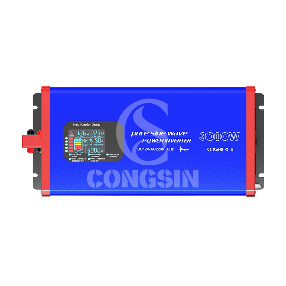
This 3000W full-power pure sine wave inverter (Model: CS3000PSW) adopts pure sine wave output technology (waveform distortion rate <2%), and the output power is highly consistent with mains power quality. It can safely drive high-power precision loads such as air conditioners, refrigerators, medical instruments, and small industrial equipment, avoiding equipment malfunctions or shortened service life caused by unstable waveforms. The device supports DC 12V input (compatible with 10.5V-14.8V wide voltage), continuously outputs 3000W full power, and has a peak power of 6000W, easily coping with the instantaneous startup impact of high-power devices; it is equipped with 4 AC universal sockets (max current 16A) + 2 USB 3.0 fast-charging ports (22.5W per port) to meet the simultaneous power supply needs of multiple devices. Built-in six-fold safety protection (overload, overvoltage, undervoltage, short circuit, overtemperature, reverse connection), combined with dual intelligent silent cooling fans (noise ≤45dB), it achieves the triple advantages of "high power + high safety + low noise," suitable for home emergency, outdoor engineering, vehicle-mounted power supply, small industrial scenarios and other fields.
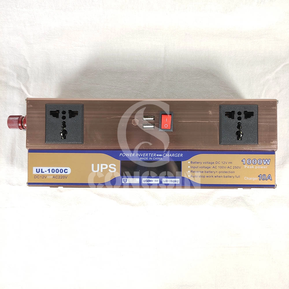
This 1000W modified sine wave inverter has UPS charging function, with DC12V input and AC220V output, and 600W rated power. Equipped with dual universal sockets, two USB ports, an LCD display, and a battery clip, it is professionally designed and has stable performance. It can provide stable AC power conversion and UPS emergency power supply for computers, small home appliances, electronic devices, etc. in home emergency, office, outdoor and other scenarios, meeting the needs of simultaneous power supply and emergency power supply for multiple devices.

This 1500W pure sine wave inverter converts DC 12V to AC 220V power, with a rated power of 1500W and a peak power of 3000W. Equipped with dual fans, LCD display, QC3.0 and PD Type-C fast charging ports, and remote control capability for stable and intelligent power output.

Our CS2000BIG 2000W modified sine wave inverter is a high-power power conversion device that converts DC 12V from batteries into AC 220V electricity. It is designed for heavy-duty use, featuring 2 AC sockets to power multiple high-power devices simultaneously, 2 cooling fans for efficient heat dissipation, and battery terminal wire for stable connection. With its robust construction and large capacity, it is an ideal solution for powering tools, appliances, and equipment in various scenarios, from industrial use to home emergencies.
Get in Touch with Our Team
You can also communicate with us directly through our online contact form. Please fill in the following information, and our team will contact you as soon as possible after receiving your message.

CONGSIN is a trusted OEM factory for power inverters, solar charge controllers, and DC converters. Reliable solutions for global B2B buyers.
 High Quality
 7/24 Service
 Guaranteed Warranty
© 2025 Congsin. All Rights Reserved.
 WeChat
 Scan QR Code
sin cong
teaimei10
Whatsapp: +8618028086791
Scan QR Code